Any experienced mold maker can manufacture mold sets for low pressure molding. Certain aspects of low-pressure mold set manufacturing differs from high-pressure mold sets, including things like materials, dimensions, cavity design, and more. We will take you through each element of the process for a full picture on how your mold set layout is designed.
Mold sets for low pressure molding are normally manufactured from 7075 aluminum. The polyamide molding materials are non-abrasive. This combined with the low injection pressures results in negligible wear on the mold set. Aluminum is cost effective to machine and excellent at dissipating heat resulting in shorter cycle times. High wear areas where components are inserted should have steel inserts. Mold sets for very high production rates can be manufactured from P-20 material, or any other conventional tool steel.
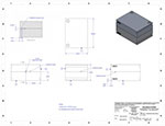
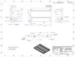
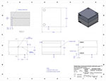
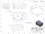
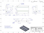
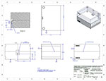
Mold set guides shall be approximately 35 mm long with 6 mm long tapered lead. (1.5” long with ¼” long tapered lead). Two different diameters shall be used such as 9 mm and 10 mm respectively. Refer to the following drawings for examples:
The design and surface texturing of the individual mold set cavities follow conventional mold making guidelines. It is important to position the parting line so that the molded components stay in the lower mold half, when the mold set is opened. This may require a stepped parting line for some applications. It is often possible to avoid the use of locating pins as the low-pressure fill of the cavity is unlikely to dislocate components. When circuit boards are over-molded, these can be positioned by locating pins if necessary.
For some applications where holes from locating pins are unacceptable in the molded parts, a two-step over-mold should be considered. One side/portion of the component is over-molded first, then the other side/portion. These mold sets will have two different cavities and components are moved from the first to the second cavity for completion.
Air vents should be 0.05 mm (0.002”) deep and up to 2.5 mm (0.1”) wide. Larger parts will require several air vents from each cavity. The vents should generally be located at the top of the cavity opposite to the gate. For components that protrude more than 1/4” above the parting line, use inserts or stepped parting line to allow for venting from top of cavity.
When shutting off around cables and wires, guides are required to facilitate positioning of the components. Shut-offs around wires and cables shall normally be in the parting line. Shut off around wires is normally 6 to 8 mm long and around cables 8 to 12 mm long. Wire/cable guides are often best made as a trough, which is two cable diameters deep and positioned “outboards” to the actual shut off.
Use steel inserts for shutting off around steel components, such as connectors.
The polyamide materials can contract some 10% when they go from liquid to solid state. It is critical that the runner / gate system allows packing of material during this phase change.
The runners will be slightly oval to release easier. A typical runner is made with a 6 mm (1/4”) ball end mill, 2.7 mm (0.106”) deep in each mold half.
A normal gate is 1.5 to 2.0 mm diameter by 0.5 mm long (60 to 80 thou round by 30 thou long). Gates should taper towards the runner to ensure that gate stays on the runner after removal.
Most production mold sets utilize ejector systems. The design follows conventional guidelines: Guide-pins and ejector-pins are sandwiched in between a base plate and a retainer plate. This sandwiched arrangement slides on shoulder bolts with return springs. Typical ejector stroke ranges from 3 to 10 mm depending on the application. Refer to mold set drawings for center of machine ejector system.
Mold sets for Mold-Man® Machines do not require any cross drilling for cooling. The aluminum mold platens are prepared for water cooling via an auxiliary chiller.
Release agent is required for the mold sets. A new mold set may require application of this release agent several times hourly or daily. Extensive research has gone into selecting the optimum release agent for this technology.
For more information on mold set layouts or other MoldMan Systems™ products and services, contact a representative today.